|
Nitric Oxide Planar Laser-Induced Fluorescence (NO PLIF)
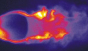
The figure below shows an experimental image of the upper-surface flow structure on a fuselage-only X-33 wind tunnel model at Mach 10, obtained at NASA Langley Research Center. The nitric oxide was seeded into the tunnel flow from the nose of the model. Flow is from top left to bottom right. The false-color image allows visualization of the counter-rotating wake vortex structure.
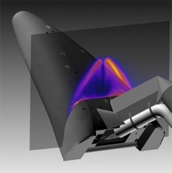
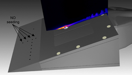
This next image shows the flow of a trace of NO seeded into the boundary layer flowing over a flat plate with a small protruding ‘trip’ that forces the flow to transition to from laminar to turbulent. Flow is from left to upper right across the plate. A prior experiment with no trip showed a smooth, laminar flow across the full length of the plate. These trips were designed to simulate conditions of a recent space shuttle flight were a protruding piece of “gap filler” had to be removed in an on-orbit space walk by the astronauts so that the flow would not transition to turbulence prematurely, which might have resulted in the loss of the shuttle due to excessive heating. The above experiment was a recent demonstration experiment, showing how NO PLIF could contribute to this important area of research.
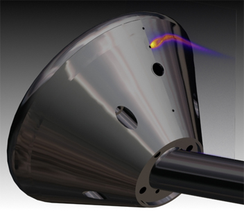
In the following image, a “Crew Exploration Vehicle” model, similar to the Apollo command module capsule was tested in a Mach 10 wind tunnel. The false-color plume shows PLIF of NO-seeded nitrogen simulating a Reaction Control System (RCS) Jet use to steer the vehicle during entry. The flow is from top left to bottom right. At higher flowrates, the jet became turbulent. The trajectory, shape and flapping of this jet can be characterized by the NO PLIF method and will be used to compare with aeronautical and aeroheating models used to design the new CEV which will return astronauts from the Moon and Mars.
|