| |
Projection Moiré Interferometry
All PMI projector systems constructed for use in LaRC wind tunnels employ broadband infrared (IR) laser diodes as the illumination source. Although laser illumination has the potential to cause speckle noise in the acquired PMI data images, diodes with 3 nm or greater emission line widths are used to virtually eliminate this problem. The use of laser diodes provides numerous advantages over strobes, flash lamps, light emitting diodes, and other laser sources. Laser diodes provide the high output power needed for illumination of large areas, and, when used with appropriate receiving camera filters, allow for lights-on facility operation without loss of projected grid line contrast. Laser diodes also have small packaging and are very robust under harsh operating conditions. In addition to providing high levels of continuous wave (CW) output power, laser diodes can be randomly pulsed to provide high intensity illumination for short time durations. This capability can be used to freeze the model position when excessive model dynamics are present, and to conditionally sample the model deformation.
Using diodes lasing in the near-IR allows PMI to be operated simultaneously with the wind tunnel optical measurement techniques shown in Table 1. By emitting at a discrete, isolated wavelength and using appropriate band-pass filters on receiving video cameras, the PMI system light can be isolated from light used by the other techniques. Thus tunnel run time can be minimized by acquiring PMI data while simultaneously acquiring other pressure, temperature, or flow velocity data.
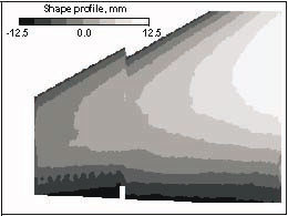
Figure 4.
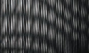
Image processing routines are then used to remove camera perspective distortion and interfere the acquired images with a computationally generated reference grid, resulting in interferograms containing moiré fringes, figure 3.
These fringe patterns are further processed offline to obtain a quantitative, spatially continuous representation of the model surface shape or deformation, as shown in figure 4.
PMI projector systems can use any incoherent light source for grid line projection. For example, conventional slide projectors are often used in laboratory PMI systems. Unfortunately, commercially available slide, micromirror, or liquid crystal display-type units will not perform adequately for a for a majority of wind tunnel applications. These projectors are often too large to fit into wind tunnel optical access ports, and are not robust enough to withstand the temperature, pressure, and vibration extremes present in most tunnels. These projectors also do not provide the illumination necessary to acquire model deformation measurements in a lighted test section, or enough light intensity to acquire short exposure measurements.
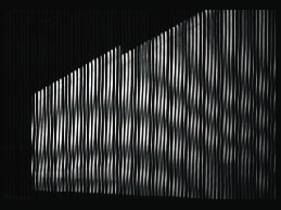
Figure 4.
PMI systems are calibrated using a flat calibration plate installed in the facility prior to model installation. For a typical sting mounted model configuration, the calibration plate is installed parallel to the test section floor at the mean vertical height of the model surface to be measured. Both sides of the plate are painted flat white, but one side has a square array of black dots (typically 30-x 30 dots) painted at a known, constant spacing. The card is oriented such that the dots can be viewed by the PMI video camera, and is illuminated by the PMI projector system with the Ronchi ruling removed. Several images of the dot target are acquired and averaged. The average dot card image is then used to determine image warping coefficients used to remove perspective and optical distortions associated with the PMI video camera and lens. After the dot card images have been obtained, the card is flipped so the remaining flat white side of the target can be viewed by the video camera. The Ronchi ruling is reinstalled in the projection system, and grid lines are projected onto the flat white surface. The target is then pitched to known angles, measured by a precision accelerometer, and images of the grid lines projected onto the target are acquired at each known pitch angle. The image sets acquired at each pitch angle are averaged, and the average images are used to determine the moiré fringe contour interval. The fringe contour interval, typically expressed in mm/fringe, is subsequently used by the image processing software to convert the computed fringe patterns to dimensional model shape or deformation data. A wind-off pitch sweep of the model at tunnel operating conditions can be performed to further refine the calibration.
|