| |
|
|
| |
|
|
| |
|
|
| |
|
| |
|
|
| |
|
Virtual Diagnostics Interface (ViDI) Powerpoint
+ Download |
| |
|
|
| |
|
|
Virtual Diagnostics Interface (ViDI)
Future Development:
Increase the level of automation for importing and aligning the data sets in the virtual environment (utilizing information embedded by Seamless Data Transfer, see below). Add robustness and ease of use to the CFD import and visualization techniques, and provide a common set of tools to analyze the CFD along with the disparate forms of experimental data in a unified environment.
ViDI Part IV – Behind the Scenes with Seamless Data Transfer
Ultimately, a suite of tools under the ViDI moniker can be deployed at a given facility to augment the planning, operation, and analysis of experimental and computational data. One of the greatest obstacles to implementation of such a system today is the various and numerous file formats and methods of data organization that exist. Just as so many CFD file formats exist, each instrument has been developed with its own file format, unfettered by the concept of working in unison with another instrument system. Seamless Data Transfer is a method of bridging that gap. It is an architecture for translating and organizing data from each source in a way that is easily cataloged, compressed, and then retrieved. Suitable tags will exist to route that data in an intelligent fashion to the tools that request it. When ultimately complete, the instrumentation data acquisition will generate the raw measurement data, with data processing and visualization stages adding relevant information. Thus, the process of organizing the data will be invisible to the user.
Readiness Level – Very Early Stages
The architecture for SDT has been laid out in a broad sense, with general file formats chosen. Some programming work has gone into creating these files, and the types of data headers that will be required. However, Seamless Data Transfer is envisioned as the next phase of ViDI development, with the first examples of this capability to be demonstrated in the next year.

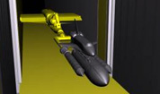
Figure 5. Laser light sheet projected onto the side of the IGES shuttle stack CAD file from Johnson Space Center.
|


